
One Cable, Four Networks
The rack is assembled and the hardware is in place. Now the software starts.
This is the first episode of Script Happens, a new series on The Vrain Lab about homelab automation with OpenWrt, k0s, and network configuration. It covers practical experiments, scripting, debugging, and infrastructure. Before any automation can happen, the network needs a design. This post covers that design and the mistakes it took to get there.
The Goal
I wanted a network with three properties:
- One trusted VLAN for my workstation, with access to the other VLANs through SSH and explicitly allowed ports, and full internet access.
- One isolated VLAN for the future Kubernetes cluster, which will run an AI-assisted trading bot.
- One isolated VLAN for another Kubernetes cluster, which will run a smart home assistant.
The two isolated VLANs cannot reach each other, cannot reach my home LAN, and cannot be reached from outside. A trading bot and a home assistant have nothing to say to each other. Keeping them apart limits the damage if one of them misbehaves.
The Layout
| VLAN | Purpose | Subnet |
|---|---|---|
| 1 (untagged) | Home LAN and OpenWrt uplink | 192.168.178.0/24 |
| 10 | Workstation and management | 192.168.10.0/24 |
| 20 | Kubernetes and trading bot | 192.168.20.0/24 |
| 30 | Smart home assistant | 192.168.30.0/24 |
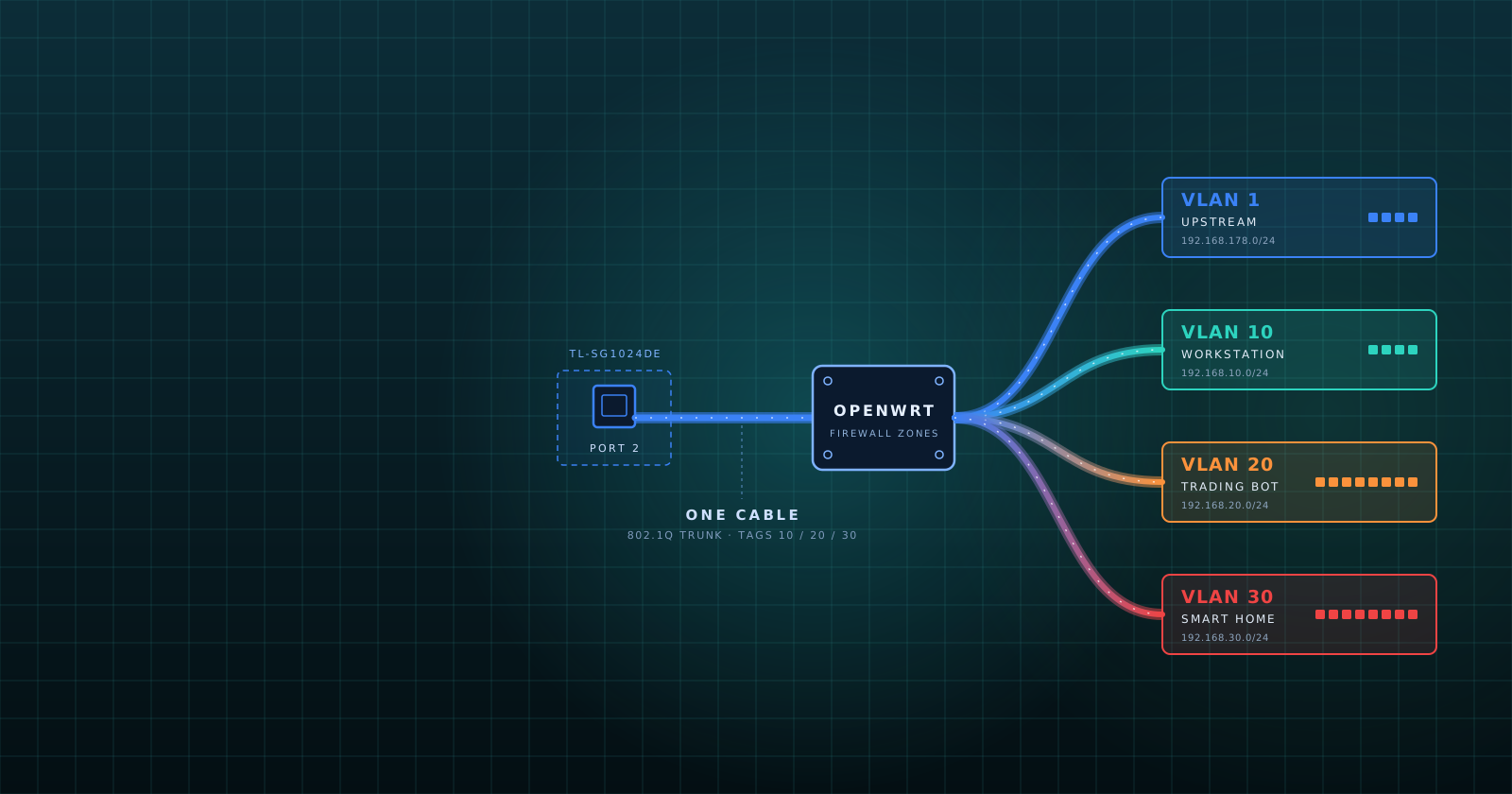
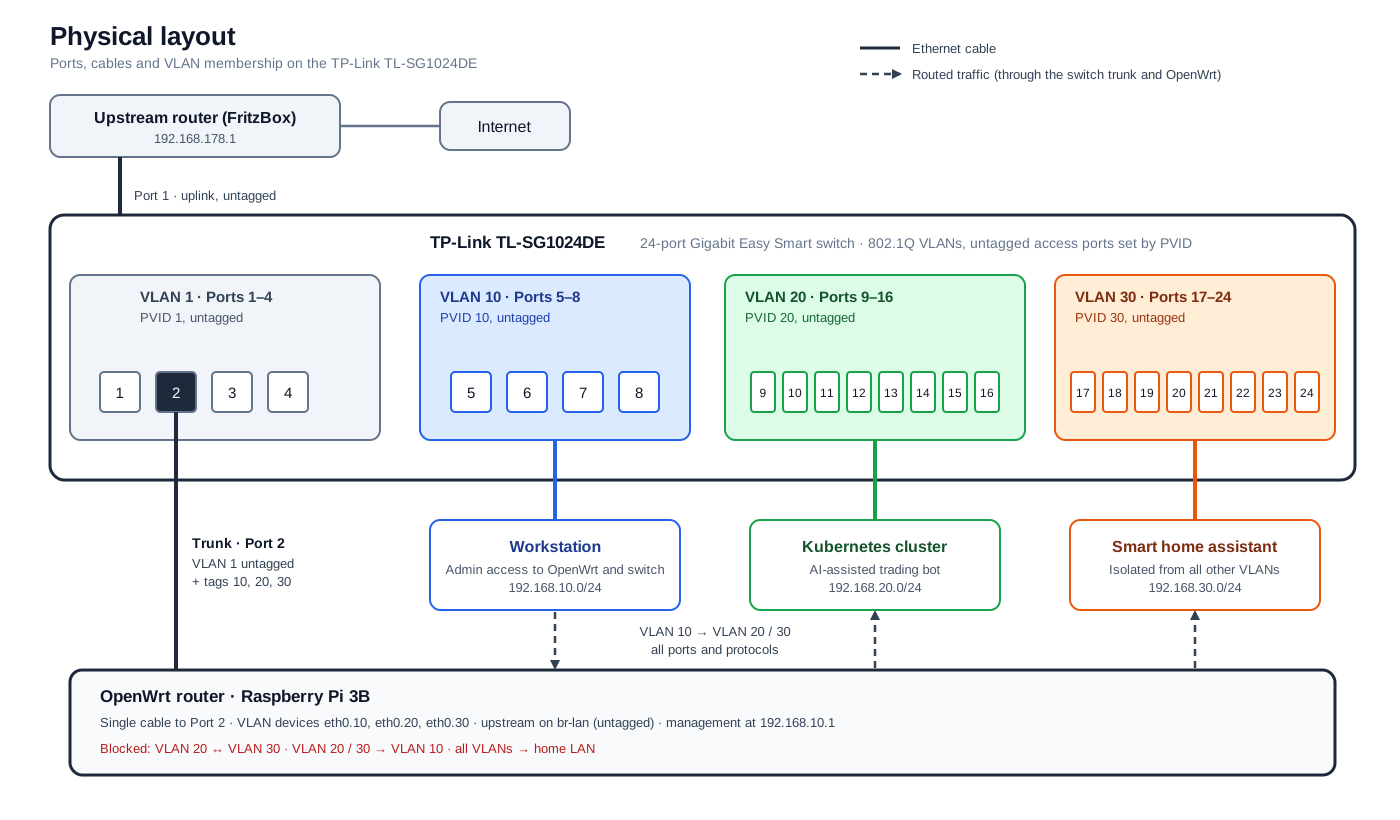
The Raspberry Pi 3 running OpenWrt sits on VLAN 1 and routes between all four networks. It connects to the switch with a single cable, a trunk that carries the untagged upstream traffic plus 802.1Q tags for VLANs 10, 20, and 30. This design is called router-on-a-stick.
The Switch
The TP-Link TL-SG1024DE has no API, so I configure it through the web interface. Two pages do all the work.
The 802.1Q VLAN table defines which ports belong to which VLAN:
- VLAN 1: ports 1–4, untagged.
- VLAN 10: ports 5–8 untagged, port 2 tagged.
- VLAN 20: ports 9–16 untagged, port 2 tagged.
- VLAN 30: ports 17–24 untagged, port 2 tagged.
Port 2 is the trunk to the OpenWrt Pi. It is a member of every VLAN, tagged for 10, 20, and 30, and untagged for VLAN 1.
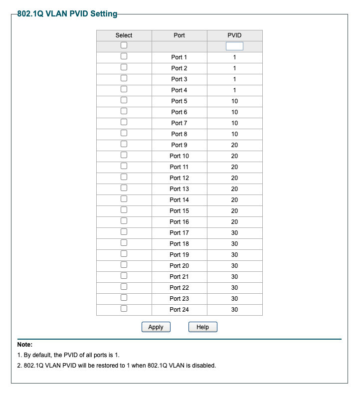
The PVID table decides which VLAN an untagged frame joins when it enters a port:
- Ports 1–4 use PVID 1.
- Ports 5–8 use PVID 10.
- Ports 9–16 use PVID 20.
- Ports 17–24 use PVID 30.
A device plugged into ports 5–8 needs no VLAN configuration. The switch tags its traffic for VLAN 10 on entry. The same applies to ports 9–16 for VLAN 20 and ports 17–24 for VLAN 30. VLAN membership comes from the port a device is plugged into, not from the device.

The Router
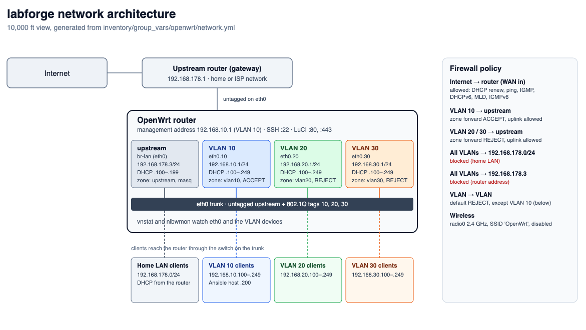
OpenWrt terminates all four networks:
- Upstream:
br-lanoneth0at 192.168.178.3, taking its uplink from the home router at 192.168.178.1 and masquerading outbound traffic. - VLAN 10, 20, and 30: the VLAN devices
eth0.10,eth0.20, andeth0.30, with gateway addresses 192.168.10.1, 192.168.20.1, and 192.168.30.1. Each network serves DHCP from .100 to .249. This is pretty much default settings already configured by creation and for my small home lab generous - Management: SSH and LuCI are reachable at 192.168.10.1, on the workstation VLAN.
Each VLAN is a firewall zone with its own forwarding policy:
- VLAN 10 forwards to upstream with ACCEPT. It is the only VLAN that can reach the others.
- VLAN 20 and 30 forward with REJECT. They can use the uplink for internet access.
- All VLANs are blocked from the home LAN (192.168.178.0/24) and from the router’s upstream address (192.168.178.3).
- VLAN to VLAN traffic is rejected by default. VLAN 10 is the only exception: it can reach VLANs 20 and 30 on allowed ports.
The built-in radio is disabled. The router has no wireless network, so every client reaches it through the switch.
Locked Out, Ten Times
The design above looks clean. Getting there was not.
My first approach was to change the OpenWrt configuration by hand, step by step, as I thought it should work. That approach cost me. I locked myself out of the system at least ten times. Change the wrong interface, VLAN, or firewall rule, and the management address disappears along with the session you are using to fix it.
Twice I locked myself out of the TP-Link web interface itself, and both times I had to reset both devices.
The two resets were not equal:
- Raspberry Pi 3: an easy recovery. OpenWrt runs from a prebuilt image on the microSD card, so I reflashed the card and started over in minutes.
- TP-Link switch: a physical reset to factory defaults. The VLAN table and every PVID were gone, and I had to rebuild the whole configuration from scratch through the web interface.
The switch reset was the biggest pain of the entire project. Every lockout there meant repeating the same manual work: recreate the VLANs, assign each port, and set each PVID again.
The lesson is simple. On a VLAN-aware switch, the port you manage it from is also part of the configuration. Change it carelessly and you have cut the branch you are sitting on.
A Known Limit
The Raspberry Pi 3 has a single Ethernet port, and it runs at 100 Mbit/s. That is the ceiling for all routed and inter-VLAN traffic, and the whole trunk shares it. For this lab it is sufficient. The switch is Gigabit, so traffic inside a VLAN runs at full speed. Only traffic that crosses the router hits the limit. If the trading cluster or the smart home ever outgrows it, the router is the first component to replace.
From Manual to Automated
Once OpenWrt reached the state I wanted and all my manual tests passed, I took a backup of the working configuration. That backup is the baseline. After ten lockouts, I decided the router should never be configured by hand again. From here on, an automated provisioner builds the configuration, so I can rebuild it from a known state instead of repeating my mistakes. The next article shows how.
AI in This Series
From here on, AI is part of my workflow. I use it to double-check my ideas before I build them and to write the small, tedious code: tests, idempotency checks, and glue scripts.
It also takes on the discipline that is tedious to maintain alone. A homelab has no team, no review process, and no sprint planning. Applying design patterns and a proper software methodology by hand would cost more effort than the lab itself, so AI drives that part.
Later it goes into the software that runs on this lab, classifying content so software decisions rest on better information.
The decisions stay mine. This lab is also where I put the last two years of building AI solutions to work and refresh what I learned. I will show where AI helps and where it does not.
What’s Next
The network design is done, and the working configuration is backed up. Next comes the part this series is named for: turning that design into an automated, repeatable setup.
The metal is in place and the network has a plan. Now let’s see what the scripts can do.
Comments
Join the discussionNo comments yet. Be the first to comment.
Script happens
Automation, configuration, and orchestration: making homelab hardware work with Ansible, OpenWrt, Kubernetes, and a healthy dose of debugging.